7.2
general documentation
Examples of data settings for radiative transfers

Activation of the module

The module can be activated in the usppmo routine in cs_user_parameters.f90. The corresponding keyword is iirayo in the cs_glob_rad_transfer_params structure.

This member can take the values:

  • iirayo = 0: module desactivated.
  • iirayo = 1: the module is activated and the Discrete Ordinates Method is used.
  • iirayo = 2: the module is activated and the P1 model is used.

Radiation module specific parameters.

When the module is activated, its specific input parameters should be set in the cs_user_radiative_transfer_parameters function of the cs_user_radiative_transfer.c file.

Calculation options for the radiative transfer module.

Radiative transfer parameters may be defined using the cs_user_radiative_transfer_parameters function.
/* indicate whether the radiation variables should be
initialized (=0) or read from a restart file (=1) */
/* Update period of the radiation module */
- 1, /* nt_start */
-1, /* nt_end */
5, /* interval */
true, /* at start */
false); /* at end */
/* Quadrature Sn (n(n+2) directions)
1: S4 (24 directions)
2: S6 (48 directions)
3: S8 (80 directions)
Quadrature Tn (8n^2 directions)
4: T2 (32 directions)
5: T4 (128 directions)
6: Tn (8*ndirec^2 directions)
*/
/* Number of directions, only for Tn quadrature */
/* Method used to calculate the radiative source term:
- 0: semi-analytic calculation (required with transparent media)
- 1: conservative calculation
- 2: semi-analytic calculation corrected
in order to be globally conservative
(If the medium is transparent, the choice has no effect) */
/* Verbosity level in the log concerning the calculation of
the wall temperatures (0, 1 or 2) */
/* Verbosity mode for the radiance (0, 1 or 2) */
/* Compute the absorption coefficient through Modak (if 1 or 2),
or do not use Modak (if 0).
Useful ONLY when gas or coal combustion is activated
- imodak = 1: ADF model with 8 wave length intervals
- imodak = 2: ADF model with 50 wave length intervals */
/* Compute the absorption coefficient via ADF model
Useful ONLY when coal combustion is activated
imoadf = 0: switch off the ADF model
imoadf = 1: switch on the ADF model (with 8 bands ADF08)
imoadf = 2: switch on the ADF model (with 50 bands ADF50) */
/* Compute the absorption coefficient through FSCK model (if 1)
Useful ONLY when coal combustion is activated
imfsck = 1: activated
imfsck = 0: not activated */
/* Activate 3D radiative models for atmospheric flows
atmo_model |= CS_RAD_ATMO_3D_INFRARED: Infrared
atmo_model |= CS_RAD_ATMO_3D_DIRECT_SOLAR: direct solar
atmo_model |= CS_RAD_ATMO_3D_DIFFUSE_SOLAR: diffuse solar
*/

Radiative transfer boundary conditions

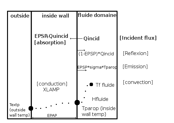
radiative_tr_sketch.gif
Sketch of thermal flux in boundary walls

The radiative boundary condition is based on the calculation of a new wall temperature. This temperature is computed with a thermal flux balance:

\[{ Q_{conduction} = Q_{convection} + (Q_{rayt_{absorption}} - Q_{rayt_{emission}}}) \]

Therefore :

\[ \dfrac{xlamp}{epap} (T_{fluid} - T_{wall}) = h_{fluid} (T_{fluid} - T_{wall}) + epsp (Q_{incid} - \sigma * T_{wall}) \]

Note
In code_saturne the flux is positive when it is oriented from inside to outside.
Body Emissivity
polished steel 0.06
oxidized steel 0.80
steel rough 0.94
polished aluminium 0.04
oxidiezd aluminium (inside) 0.09
oxidized aluminium (wet air)0.90
brick 0.93
concrete 0.93
paper 0.8 to 0.9
water 0.96

Boundary faces identification

Boundary faces may be identified using the getfbr function, or preferrably, through boundary zones, defined using the GUI or the cs_user_zones function..

Initialization and finalization

The following declaration and initialization block needs to be added for the following examples:

Remaining initialisation

ivar: number of the thermal variable

const cs_lnum_t ivart
= cs_field_get_key_int(fth, cs_field_key_id("variable_id")) - 1;

Min and Max values for the wall temperatures (clipping otherwise)

$ T_{min} $ and $T_{max} $ are given in Kelvin.

*tmin = 0.0;
*tmax = cs_math_big_r + tkelvi;

Assign boundary conditions to boundary wall

Zone definitions

For each boundary face face_id, a specific output (logging and postprocessing) zone id may be assigned. This allows realizing balance sheets by treating them separately for each zone. By default, the output zone id is set to the general (input) zone id associated to a face.

To access output zone ids (both for reading and modifying), use the cs_boundary_zone_face_zone_id function.

Wall characteristics

Warning
The unit of the temperature is the Kelvin

Mandatory data

  • isothp(ifac) boundary face type
    • CS_BOUNDARY_RAD_WALL_GRAY: Gray wall with temperature based on fluid BCs
    • CS_BOUNDARY_RAD_WALL_GRAY_EXTERIOR_T: Gray wall with fixed exterior temperature
    • CS_BOUNDARY_RAD_WALL_REFL_EXTERIOR_T: Reflecting wall with fixed outside temperature (same as Gray wall with zero emissivity)
    • CS_BOUNDARY_RAD_WALL_GRAY_COND_FLUX: Gray wall with fixed conduction flux
    • CS_BOUNDARY_RAD_WALL_GRAY_REFL_FLUX: Reflecting wall with fixed conduction flux

Other data (depending of the isothp)

  • rcodcl = conduction flux
  • epsp = emissivity
  • xlamp = conductivity ( $W.m^{-1}.K^{-1}$)
  • epap = thickness ( $m$)
  • textp = outside temperature ( $K$)

Examples of boundary conditions

Here is a list of examples:

Gray or black wall with profil of fixed inside temperature

For wall boundary faces, selection criteria: color 1

zone = cs_boundary_zone_by_name("wall_1");
for (cs_lnum_t ilelt = 0; ilelt < zone->n_elts; ilelt++) {
cs_lnum_t face_id = zone->elt_ids[ilelt];
if (bc_type[face_id] == CS_SMOOTHWALL) {
/* logging zone number */
izfrdp[face_id] = 51;
/* Type of condition: gray or black wall with fixed interior
temperature (based on main temperature BC's) */
isothp[face_id] = CS_BOUNDARY_RAD_WALL_GRAY;
/* Emissivity */
epsp[face_id] = 0.1;
}
}

Gray or black wall with fixed outside temperature \f$ T_{ext} \f$

For wall boundary faces, selection criteria: color 2

zone = cs_boundary_zone_by_name("wall_2");
for (cs_lnum_t ilelt = 0; ilelt < zone->n_elts; ilelt++) {
cs_lnum_t face_id = zone->elt_ids[ilelt];
if (bc_type[face_id] == CS_ROUGHWALL) {
/* logging zone number */
izfrdp[face_id] = 52;
/* Gray or black wall with fixed exterior temperature */
/* Emissivity */
epsp[face_id] = 0.9;
/* Conductivity (W/m/K)*/
xlamp[face_id] = 3.0;
/* Thickness (m)*/
epap[face_id] = 0.1;
/* Fixed exterior temperature: 473.15 K */
textp[face_id] = 200. + tkelvi;
}
}

Reflecting wall (\f$ epsp = 0 \f$) with fixed outside temperature \f$ T_{ext} \f$

For wall boundary faces, selection criteria: color 3

zone = cs_boundary_zone_by_name("wall_3");
for (cs_lnum_t ilelt = 0; ilelt < zone->n_elts; ilelt++) {
cs_lnum_t face_id = zone->elt_ids[ilelt];
if (bc_type[face_id] == CS_SMOOTHWALL) {
/* log zone number */
izfrdp[face_id] = 53;
/* Type of condition: reflecting wall with fixed outside temperature */
/* Conductivity (W/m/K) */
xlamp[face_id] = 3.0;
/* Thickness (m)*/
epap[face_id] = 0.10;
/* Fixed outside temperature: 473.15 K */
textp[face_id] = 200.0 + tkelvi;
}
}

Gray or black wall and fixed conduction flux through the wall

For wall boundary faces which have the color 4:

\[ \begin{array}{rcl} \frac{\texttt{xlamp}}{\texttt{epap}} \cdot (T_{wall} - T_{ext}) &=& \text{fixed conduction flux in } W.m^{-2} \\ &=& \texttt{rodcl(ifac,ivar,3)} \end{array} \]

If the conduction flux is zero then the wall is adiabatic. The array $ \texttt{rcodcl(ifac,ivar,3)}$ has the value of the flux.
Flux density (< 0 if gain for the fluid)

  • For temperature $T$, in $ W.m^{-2}$:

\[ rcodcl(ifac,ivar,3)=C_p (viscls+\frac{visct}{\sigma})\cdot \grad{T}\cdot \vect{n} \]

  • For enthalpy $h$, in $ W.m^{-2} $:

    \[ RCODC(IFAC,IVAR,3)=(viscls+\frac{visct}{\sigma})\cdot \grad{H} \cdot \vect{n}\]

zone = cs_boundary_zone_by_name("wall_4");
for (cs_lnum_t ilelt = 0; ilelt < zone->n_elts; ilelt++) {
cs_lnum_t face_id = zone->elt_ids[ilelt];
if (bc_type[face_id] == CS_SMOOTHWALL) {
/* log zone number */
izfrdp[face_id] = 54;
/* Type of condition: gray or black wall with fixed conduction
flux through the wall */
/* Emissivity */
epsp[face_id] = 0.9;
/* Conduction flux (W/m2) */
rcodcl[face_id + ivart * n_b_faces + 2 * nvar * n_b_faces] = 0.0;
}
}

Reflecting wall and fixed conduction flux through the wall

For wall boundary faces which have the color 5:

\[ \frac{xlamp}{epap} \cdot (T_{wall} - T_{ext}) = \text{fixed conduction flux} \]

and $ epsp = 0 $

If the conduction flux is zero then the wall is adiabatic. Flux density (< 0 if gain for the fluid)

  • For temperatures $T$, in $ W.m^{-2} $:

    \[ rcodcl(ifac,ivar,3) = C_p (viscls+\frac{visct}{\sigma}) \cdot \grad{T}\cdot \vect{n} \]

  • For enthalpies $h$, in $ W.m^{-2} $:

    \[ rcodcl(ifac,ivar,3) = (viscls+\frac{visct}{\sigma}) \cdot \grad{H} \cdot \vect{n} \]

zone = cs_boundary_zone_by_name("wall_5");
for (cs_lnum_t ilelt = 0; ilelt < zone->n_elts; ilelt++) {
cs_lnum_t face_id = zone->elt_ids[ilelt];
if (bc_type[face_id] == CS_SMOOTHWALL) {
/* log zone number */
izfrdp[face_id] = 55;
/* Type of condition: reflecting wall with fixed conduction
flux through the wall */
/* Conduction flux (W/m2)*/
rcodcl[face_id + ivart * n_b_faces + 2 * nvar * n_b_faces ] = 0.0;
}
}

Absorption coefficient and net radiation flux

The absorption coefficient and the net radiation flux for the radiative module can be defined in cs_user_radiative_transfer.c through the cs_user_rad_transfer_absorption and Net radiation flux subroutines.

Absorption coefficient

The absorption coefficient is defined in cs_user_rad_transfer_absorption.

Computation of the absorption coefficient

/*
* Absorption coefficient of the medium (m-1).
*/
for (cs_lnum_t cell_id = 0; cell_id < cs_glob_mesh->n_cells; cell_id++)
ck[cell_id] = 0.;

Net radiation flux

The net radiation flux is computed in Net radiation flux.

Local variables to be added

Initialization

At the end of the subroutine, if iok is different from zero, some faces have been forgotten and the calculation stops.

/* Initializations */

Computation of the net radiation flux

/* Net flux dendity for the boundary faces
* The provided examples are sufficient in most of cases.*/
/* If the boundary conditions given above have been modified
* it is necessary to change the way in which density is calculated from
* the net radiative flux consistently.*/
/* The rule is:
* the density of net flux is a balance between the emitting energy from a
* boundary face (and not the reflecting energy) and the absorbing radiative
* energy. Therefore if a wall heats the fluid by radiative transfer, the
* net flux is negative */
for (cs_lnum_t ifac = 0; ifac < cs_glob_mesh->n_b_faces; ifac++) {
/* Wall faces */
if ( bc_type[ifac] == CS_SMOOTHWALL
|| bc_type[ifac] == CS_ROUGHWALL)
net_flux[ifac] = eps[ifac] * (qincid[ifac] - stephn * pow(twall[ifac], 4));
/* Symmetry */
else if (bc_type[ifac] == CS_SYMMETRY)
net_flux[ifac] = 0.0;
/* Inlet/Outlet */
else if ( bc_type[ifac] == CS_INLET
|| bc_type[ifac] == CS_CONVECTIVE_INLET
|| bc_type[ifac] == CS_OUTLET
|| bc_type[ifac] == CS_FREE_INLET) {
net_flux[ifac] = qincid[ifac] - cs_math_pi * coefap[ifac];
net_flux[ifac] = 0.0;
}
/* Stop if there are forgotten faces */
else
(__FILE__, __LINE__, 0,
"In %s:\n"
" non-handled boundary faces for net flux calculation\n\n"
" Last face: %10ld; zone = %d; nature = %d\n",
__func__,
(long)ifac,
bc_type[ifac]);
}