As usual, except for advanced models where a high level of automation is needed through specific preprocessing scripts or tools, using the GUI to define boundary conditions is recommended.
Check the pdf user's guide for details on legacy boundary condition settings and types.
Prior to defining boundary conditions, the appropriate zones should be defined. Using the GUI, this is done in the Mesh section, as an early definition of the defined zones (before the mesh is actually read or built) may be useful for many other settings, not limited to boundary conditions.
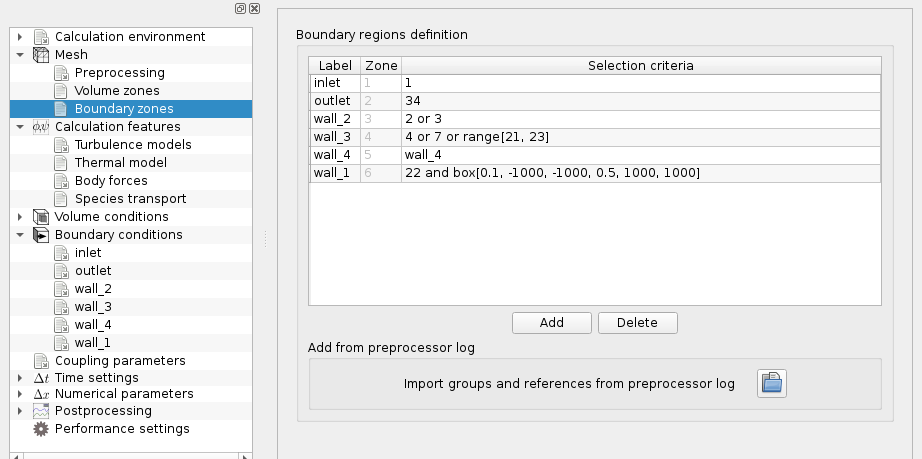
In most cases, the names of mesh groups than can be used for zone definitions faces may be read directly from preprocessor.log file created by the Preprocessor. Following an initial mesh proprocessing or verification run, these definitions can be imported directly by the GUI under the "Mesh/Boundary zones/Add from Preprocessor log" section.
For advanced cases, or when it is necessary to define zones which overlap, or whose section is based on a (possibly time-varying) function, the cs_user_zones function may be used. A few examples are also provided.
Based on the defined zones, the GUI can be used to define boundary types and conditions:
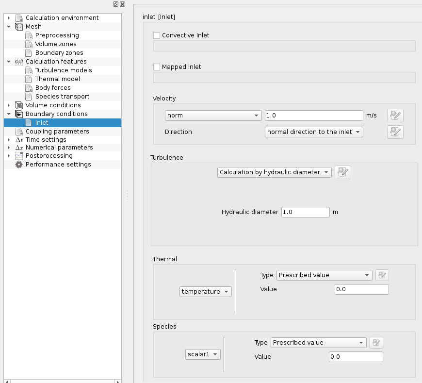
For advanced cases, user-defined functions are available, as usual. Many examples are provided.
To define or re-define zone-based boundary condition values, the cs_user_boundary_conditions_setup (or alternatively cs_user_finalize_setup_wrapper) functions may be used.
Note that at walls and when using wall laws (which is the case with most turbulence models), the boundary values prescribed through Dirichlet or Robin conditions are not currently directly appplied, but used in conjunction with the wall model. To force true Dirichlet or exchange conditions, using the legacy boundary condition settings is still needed.
The code checks the main compatibilities between the boundary conditions. In particular, the following rules must be respected:
In case of errors, if the post-processing output is activated (which is the default setting), a special error output, similar to the mesh format, is produced in order to better identify and locate boundary condition definition errors.
The cs_user_les_inflow.c user-defined function allows to generate the unsteady boundary conditions for the LES by the Synthetic Eddy Method. The basic principle of this method is illustrated in the following figure.
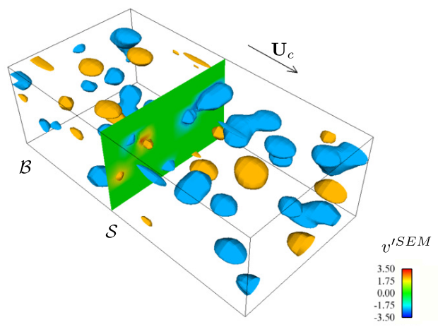
In the figure above, 


The turbulent fluctuations at the inlet are generated by a set of synthetic eddies advected across the inlet boundaries. The eddies evolve in a virtual "box" surrounding the inlet boudaries and each of them contributes to the normalized velocity fluctuations, depending on its relative position with the inlet faces and on a form function characterizing the shape of the eddies. By this way, the Synthetic Eddy Method provides a coherent flow with a target mean velocity and target Reynolds stresses at LES inlet.
In the current version of code_saturne, the Synthetic Eddy Method is not available through the GUI but only through the cs_user_les_inflow.c user file.
Use of these functions is illustrated in the generation of synthetic turbulence at LES inlets page.
The number of synthetic eddies in the "box" might be adjusted, depending on the case (in particular the size of the inlet plane and the level of turbulence). As a general rule, the greater is the better since an insufficient number can lead to an intermittent signal while some numerical tests have shown that this parameter does not have a great influence beyond a threshold value. Given the inlet of size h<up>2</up> of a shear flow at a given Reynolds number 


![\[\sigma_i=\max\left\{C\frac{\big(\frac{3}{2}R_{ii}\big)^{3/2}}{\varepsilon},\Delta\right\},\qquad
C=0.5.
\]](form_879_dark.png)

![\[\Delta=2\max_{i\le3,V\in\mathcal{V}}\Big\{\big|x_i^V-x_i^C\big|\Big\}
\]](form_880_dark.png)

For the sake of comparison, other LES inflow methods are available, in addition to the Synthetic Eddy Method: