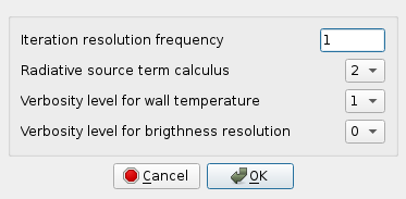
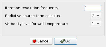
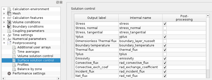
The main radiation parameters can be initialized in the GUI or in the cs_user_radiative_transfer_parameters user function (see Initialization examples). In the GUI, under the heading Thermal models, when one of the two thermal radiative transfers models is selected, see Figure 1 additional items appear. The user is asked to choose the number of directions for angular discretization, to define the absorption coefficient and specify if the radiative calculation is restarted from a checkpoint or not; see Figure 1 and Figure 3. When Advanced options is selected for both models Figure 2 and Figure 4 appear, the user must fill the resolution frequency and verbosity levels. In addition, the activation of the radiative transfer leads to the creation of a Surface solution control item under the heading Calculation control, see Figure 5, where radiative transfer variables can be selected to appear in the output log.
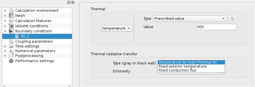
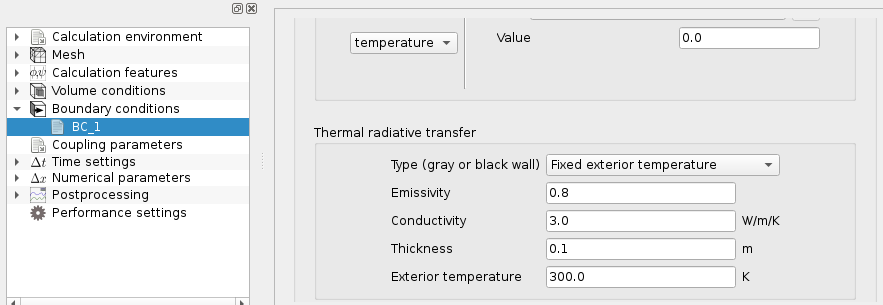
These conditions can be defined with the GUI or by programming the cs_user_radiative_transfer_bcs function; see boundary examples. In the GUI, when one of the Radiative transfers options is selected in Figure 1 and Boundary zones is defined in Mesh, it activates specific boundary conditions each time a Wall is defined, see Figure 6. The user can then choose between 3 cases. The parameters that must be specified are displayed for one of them in Figure 7.
When the absorption coefficient is not constant, the cs_user_rad_transfer_absorption functionis called at each time step. It is composed of three parts. In the first one, the user must provide the absorption coefficient of the medium in the array CK, for each cell of the fluid mesh. By default, the absorption coefficient of the medium is 0, which corresponds to a transparent medium. For more detail see Absorption

